How to Cite | Publication History | PlumX Article Matrix
Obstruction Recognition for Visually Challenged Patients
Archana*1, C. Chellaram2, M. Rajalakshmi3
1Department of Electronics and Telecommunication, Sathyabama University, Chennai-600119.India 2Department of Biomedical Engineering, Vel Tech Multi Tech Dr.RR Dr.SR Engineering College, Chennai-600 062. India 3Department of Electronics and Telecommunication, Sathyabama University, Chennai-600119.India
ABSTRACT: Currently, many researches has been carried to devise the navigation for blind people. Here, we propose an efficient system to aid the visually impaired in their navigation. User will be indicated about the nearing obustruction with closer ambiance. The basic concept behind this system is to detect the nearest hindarence through a stereoscopic sonar system and sends back vibro-tactile feedback to inform the user about its localization through a beep sound provided with voice indication for a differentiation between three sensors imbibed. The proposed system aims in increasing the mobility for visually impaired by offering various sensing abilities. The device is light, portable, but range limited to its own size.
KEYWORDS: Visually impaired; Obstruction; Steroscopic sonar System; Sound Buzzer
Download this article as:| Copy the following to cite this article: Archana, Chellaram C, Rajalakshmi M. Obstruction Recognition for Visually Challenged Patients. Biosci Biotech Res Asia 2015;12(2) |
Introduction
Eyes play a vital role in our life. All of us have seen the blind people and know the problems that they face in their life. There are about 45 million blind people in the world according to the survey of World Health Organization. In particular, these people are faced with huge difficulties moving in cities, streets, public transportation systems and shopping malls representing a hostile ever-changing environment. In such sceneraio blind people face many hinderances for their own naviagtion, due to their autonomy being limited. Generally, blind people can recognize their regular path of usage and the obstacles in which they stumble upon. In regards to this, they restrict the navigation movement among themselves as they may have hindrances in their path Based on these complications many systems are developed to help the visually impaired in their mobility.
Generally guide canes are largely used by the blind people in order to indicate the presence of an obstacle. Embedding of ultrasonic sensors, infrared sensors and laser telemetry, a cane system was developed to detect the obstacle by having an angle of incidence which covers 20º and the distance with an approximation of 50 cm. Thus the obstacle is indicated through the earphones producing the individual’s desired song which is already being recorded [1].The other system developed is a guide cane which detects the presence of an obstacle through mobile robot avoidance sensor and is indicated by a steering effect which has a stepper motor fitted inside to induce the specified effect [2]. Later on a, system was developed to indicate the presence of an obstacle by obtaining an image through a camera being fitted on the corner of the glass and thereby applying a mathematical method consisting of standardized and normalized cross correlation method and binary method to the values being noted from the image obtained, the obstacle is indicated[3].
A portable system using Ultrasonic sensor for the detection of an obstacle was developed. In this system an overcoat is designed with two ultrasonic sensors using which the presence is detected at a distance which ranges from 3cm to 3m and the field of view is limited to 60º. Once when an obstacle is detected this overcoat produces a whole body vibrating effect in order to indicate obstruction presence [4]. Another system is designed with sun glass imbibed with two cameras that helps in capturing the image of an obstacle. The image captured is sent to a palmtop and a desktop computer. A normal individual is asked to monitor the desktop computer and alerts the visually impaired about the position, depth and the accuracy of an hindrances through earphones [5].
All the above system was developed to help the visually challenged in detection and indication of an obstruction to have a safer navigation, each system have its own disadvantage. In a system using, Guide canes the sensors are being placed on the bottom which results in the damage of sensors and the obstacle is detected only when it is being touched [6]. The system using mathematical model helps in detecting an obstruction but no indications are given after detecting a hindrances. In Portable system the over coat produces a whole body vibration that leads to heart attack, stroke etc [7]
Materials and Methods
The various components being incorporated in the system are as follows
Power supply
A power supply of 5volt is produced by connecting four batteries within a case in which each battery has a charge of up to 1.2 volt A charger is provided in case of a low voltage.
Ultrasonic sensor
Ultrasonic sensors has both sender and a reciever module working on the concept of radar/Sonar.These sensor generate high frequency waves,where signals are evaluvated and sent back.time interaval is calculated between the sent signal and receiving signal to find the distance of the object. An ultrasonic sensor of model HC-SR04 is being used in the proposed system. It covers a distance of upto 0.3 to 4 meters and an angle of 600 .The sensor has four terminals- Vcc, trigger, echo and ground. The working frequency of the sensor is about 40 KHz.
The concept of working behind this is I/O trigger for at least 10microseconds higher level of signal, this specific module sends continues 8 signals which ranges abort 40 kHz to find the presence of pulse signals. Thus in such a case the test distance is given by,
Test distance = High level of time * Velocity of Sound
Microcontroller
The Microcontroller AT89C51used here is a High performance microcomputer with 4K of Flash PEROM. This device embedded on the kit is non volatile and compatible with industry standards. The specific on-chip Flash allows the program memory to be reprogrammed in-system or by a non conventional memory programmer.
The combination of 8bit CPU provided by flash on a single chip makes the Atmel AT89C51 a high microcomputer and economic solution for embedded applications. This specified controller has 32 I/O ports and is of 40 pin packing set, before setting up the kit the address, data and control signals should be based on flash programming mode for, program the AT89C51, the following points are considered, Input the desired memory location on the address lines, Input the appropriate data byte on the data lines, Activate the correct combination of control signals, Raise EA/VPP to 12V for the high-voltage programming mode. The byte-write cycle is self-timed and typically takes no more than 1.5 ms. Repeat steps 1 through 5, changing the address and data for the entire array or until the end of the object file is reached.
Voice IC-APR 9600
The APR9600 device imbibed to the kit gives a single rate of single-chip channel recording and on-volatile storage, audio capacity for 40 to 60 seconds.
This device gives a basic platform for random and sequential access of messages, selected range of samples ar being used based on the design features like storage and quality.These device are portable im many applications.this device has a mutilevelstorage capacity making the voice IC to reproduce voice signals in a natural form.the specific advantage it exculdes need for encoding and compression.No external Ic is required or backup required ,low power cosumption and a standby current is about 1uA
Sound Buzzer
In this proposed system two types of sound buzzers are being used. They are continous sound buzzer and intermediate sound buzzer for indicating the presence of the obstruction. A sound buzzer producing minimum sound is being selected which is of low cost. The pitch of the sound buzzer is about 5mm. The low frequency range is about 2 KHz and high frequency range is about 4 KHz. These two types of buzzers indicate the presence of the obstacle only when the microcontroller is being programmed for detecting the presence of the obstacle.
The working of the system starts when the power supply is being ON. Switch ON the battery supply. Once when a Vcc of 5v power Supply is given the microcontroller ATMEL 89C51 it produces a trigger pulse. This pulse is given to the ultrasonic sensor. Using this trigger pulse the ultrasonic sensor starts detecting the presence of obstruction. Ultrasonic sensors generate high frequency sound waves and evaluate the echo which is received back by the sensor. Sensors calculate the time interval between sending the signal and receiving the echo to determine the distance to an object.
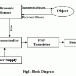
The Ultrasonic Sensor transmits the Ultrasonic waves to check the presence of hindrances so,when a obstacle comes into the range of the sensor then the ultrasonic waves hits the object and produces echo signals in reflex. Once this echo Signal is received by the ultrasonic sensor then an echo pulse is given to the micro controller to produce an output. The Microcontroller thus applies a negative voltage to the PNP transistor where it makes the flow of holes higher than the flow of electrons. Once when the negative voltage is applied to the transistor then the high signal is given to the output circuit. In the output circuit when a high signal is given then the sound buzzer starts giving beep sound to indicate the detection of the obstruction. This is the working of single sensor. The power consumption is also minimum, for a long duration of time with the low requirement of the battery supply. Obstruction detection is one of the main problems to solve to ensure safe navigation for blind users. Initially the localization on a horizontal plane is done by a combination of the left and the right side. The entire block setup on working of the proposed system is also indicated in (Fig.1)
 |
Figure 1: Block Diagram |
Results
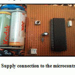
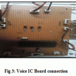
Once the components are embedded on the board, the system is verified in a testing ambience. The working of the sensor is done through the microcontroller program(Fig 2).Obstruction is indicated through the sound buzzer. Differentiation of direction between left and right is done via intermediate and continuous sound buzzer. Voice command is given for the indication of an obstacle in the centre direction (Fig 3).
 |
Figure 2: Supply connection to the microcontroller |
 |
Figure 3: Voice IC Board connection |
In Computerized Obstacle system, gives an overview of existing devices for the guidance of visually impaired pedestrians and discusses the properties of the white cane and of conventional electronic travel aids [10]. Also described are the disadvantages of using a standard mobile robot obstacle avoidance technology. The NavBelt is worn by the user around obstacles. One limitation of the NavBelt is that it is exceedingly difficult for the user to comprehend the guidance signals in time to allow fast walking and in GuideCane system, including the mechanical, electronic and software components, follows a description of the intuitive user-machine interface [11].In portable optical detection system for visually impaired people is being provided with a whole body vibration effect whenever the obstacle is being detected. Obstacle detection is one of the main problems to solve to ensure safe navigation for blind users [8]. The stereoscopic architecture of the system is used to develop new obstacle sensing abilities. Various components like vibrator, microcontroller, sensor and DAC is being used. The sonar system is based on two ultrasonic transducers mounted together. One emits an ultrasonic wave while the other measures the echo. By differentiation of the input and output signals, a microcontroller PIC16F87 computes the distance to the nearest obstacle. Then this information is transmitted as a PWM signal to the receiver.The microcontroller gathers the information from the ultrasonic transducers as Pulse Wide Modulation (PWM) signal directly proportional to the distance of the nearest obstacle whole system is depicted in the paper [9].
From the existing technology [12], the field of view has been increased to 180º horizontally that covers a cone like projected area by using ultrasonic sensor, with a distance of about 0.3 to 4 meters. The system is portable and does not have any additional huge device to be carried with the individual. The obstruction is being detected without any contact with the sensor unlike the Guide Cane technology [13]. The system does not produce any harm to the health condition of the visually impaired individual unlike the wearable obstacle detection system and also the sensors are placed in the pelvic region such that it can indicate the presence of the smaller and larger objects [14].
Acknowledgement
Authors deliver their grattitude to the management of Sathyabama University for their unremitted encouragement and to FIST-DST Program (No.SR/FST/College-189/2013) Govt. of India for laboratory facilities support.
References
- M.Benjamin.,N.A.Ali , “A laser cane for the blind”, In Proceedings of the San Diego Biomedical Symposium, volume12, pp 53-57, 2007.K.K
- Ito, M. Okamoto, J. Akita, “CyARM: an alternative aid device for blind persons”, extended abstracts on Human factors in computing systems,pp1483—1488,2005.
- Kunsoo Huh, Jaehak Park, Junyeon Hwang, Daegun Hong, “A stereo vision-based obstacle detection system in vehicles,” Optics and Lasers in Engineering, ,Vol. 46, pp. 168–178,2008.
- Jesus Garcia, Jesus Urena, Manuel Mazo, “Sensory system for obstacle detection on high-speed lines,” Transportation Research Part C , Vol.18, pp. 536–553,2010.
- Jansson,” The functions of present and future electronic travel aids for visually impaired children and adults”. In The Spanish National Organization of the Blind, Sixth International Mobility Conference,pp 59–64, 1999.
- Hahnel,W. Burgard,D. Fox,K. Fishkin, “Mapping and localization with RFID technology.” In: Proc. of the IEEE International Conference on Robotics and Automation pp.1015–1020,2004..
- Joshua Redding, Jayesh N. Amin, D.Jovanl, “A Real-time Obstacle Detection and Reactive Path Planning System for Autonomous Small-Scale Helicopters”, AIAA Guidance, Navigation and Control Conference,Vol II,pp-196-202, August 2007.
- Panuccio “A Multimodal Electronic Travel Aid Device” ICMI 02: in proceedings of the 4th IEEE International Conference on Multimodal Interfaces, IEEE Computer society Washington DC, USA, pp 39, 2002.
- Sylvain Cardin, Daniel Thalmann and Frederic “Wearable Obstacle Detection System for visually impaired People” Vexo, Virtual Reality Laboratory (VRlab).
- Nazli Mohajeri, Roozbeh Raste, “An Obstacle Detection System for Blind People” IAENG Proceedings of the World Congress on Engineering , ,London, U.K ,Vol II , July 6-8 2011.
- Sylvain Cardin, Daniel Thalmann and Frederic “Wearable Obstacle Detection System for visually impaired People” Vexo, Virtual Reality Laboratory (VRlab), Ecole Polytechnique Federale de Lausanne (EPFL),Lausanne, Switzerland) CH-1015.
- Christophe Jacquet, Yasine Belliek, “Electronic Locomotion Aids for the Blind:Towards More Assistive Systems”, IEEE,Vol-14,pp58-61, March 28-2011.
- Kitazawa,Y. Konishi,R. Shibasaki, “A Method of Map Matching For Personal Positioning Systems.” In: Proceedings of the Asian Conference on Remote Sensing ACRS, pp.726–731,2004.
- Shoval,I.Ulrich and J.Borenstein. “ Obstacle Avoidance Systems for the Blind and Visually Impaired.”, CRC Press ISBN/ISSN: 0849301408,pp.414-418,2012.

This work is licensed under a Creative Commons Attribution 4.0 International License.


