Manuscript accepted on :
Published online on: 21-12-2015
Some Problems of Designing Tethered Low-Volume Aerostat Systems
S. M. K. Bakmaev1, G. V. Tsepilov1, I. S. Vorontsov2, and V. V. Ivanov1
1TEСHNOСOMPLEKT” Closed joint-stock company, ul. Shkol'naya 10a, Dubna, Moscow oblast, 141981 Russia 2Dubna International University, ul. Universitetskaya 19, Dubna, Moscow oblast, 141980 Russia
ABSTRACT: A low-volume hybrid aerostat system project is considered. It is shows that the proposed design allows the flight altitude to be maintained at a higher wind speed as compared to the classical aerostat design.
KEYWORDS: tethered aerostat; hybrid aerostat; wind speed; lift force
Download this article as:| Copy the following to cite this article: Bakmaev S. M. K, Tsepilov G. V, Vorontsov I. S, Ivanov V. V. Some Problems of Designing Tethered Low-Volume Aerostat Systems. Biosci Biotech Res Asia 2015;12(2) |
Introduction
Aerostats were the first flying vehicles that permitted a man to go up into air. In the early 20th century giant airships surpassed airplanes in load-lifting capacity and flight range. Zeppelins became a sinister symbol of World War I. Though attempts to design and build airships still continue, they have so far failed to occupy any significant niche among other vehicles. It is tethered aerostats that have found practical application, being used to make systems for air and ground monitoring, transmission of signals, meteorological observations, etc.
This paper deals with the problems of aerodynamic design of tethered low-volume aerostats related to their ability to withstand a high wind speed.
Review of existing tethered aerostat systems
At present the leading manufacturers of tethered aerostat systems (TASs) are the American companies Lockheed Martin [1] and ТСОМ [2] and the Russian company Augur Aeronautical Center [3]. Specifications of their products are presented in Table 1.
Table 1: Specifications of modern tethered aerostat systems [1, 2, 3]
| TAS | Volume,
m3 |
Service ceiling, m |
Payload, kg |
Endurance, days |
Maximum wind speed at ceiling altitude, m/s |
||
| Lockheed Martin (USA) | |||||||
| 74K | 2100 | 1500 | до 500 | до 30 | – | ||
| 420K | 12000 | 4600 | 1000 | 30 | – | ||
| ТСОМ (USA) | |||||||
| 12М | – | 300 | 27 | 7 | 18 | ||
| 17М | – | 300 | 90 | 7 | 18 | ||
| 22М | – | 900 | 190 | 14 | 22 | ||
| 28М | – | 1500 | 385 | 14 | 22 | ||
| 32М | 1800 | 900 | 225 | 15 | – | ||
| 71М | 16700 | 4600 | 1600 | 30 | 30 | ||
| Augur Aeronautical Center (Russia) | |||||||
| Irbis | 110 | 900 | 25
(altitude 300 m) |
1 | 15 | ||
| Lynx | 450 | 1000 | 60-150 | 15 | 25 | ||
| Gepard-12 | 1200 | 1000 | 100-300 | 20 | 30 | ||
| Gepard-18 | 1800 | 1700 | 100-500 | 20 | 30 | ||
| Tiger-27 | 2700 | 1500 | 100-350 | 15 | 42 | ||
| Tiger-40 | 4000 | 3000 | 200-500 | 15 | 42 | ||
| Puma | 12000 | 4000 | 2250 | 30 | 35 | ||
High-volume TASs are mainly used for military and special strategic tasks. Since 1992 the United States has been operating TARS (Tethered Aerostat Radar System) for surveillance purposes on the southern US border. Lockheed Martin 420K aerostats with on-board radars are operated on the border with Mexico, in Florida, and on the Caribbean islands to detect smuggling and drug trafficking [1, 4]. Various TAS uses are considered in detail in [5, 6, 7].
Short-term or local tasks (e.g., monitoring of an area of a few kilometers) can be solved using aerostat systems with a volume of about 10 m3, payload of a few kilograms, and a ceiling of hundreds of meters. The obvious advantage of these small-sized TASs is a relatively low cost of their manufacture and operation.
All TASs listed in Table 1 have a similar aerodynamic design: a drop-shaped streamline body with the empennage to give stability to the aerostat (Fig. 1).
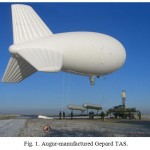 |
Figure 1: Augur–manufactured Gepard TAS. |
The ability of these aerostats to maintain the flight altitude in winds entirely depends on their size.
Stability of the Aerostat in winds
Let us consider the forces acting on the aerostat (Fig. 2). For simplicity, we assume the horizontal direction of the wind.
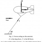 |
Figure 2: Forces acting on the aerostat. X is the drag force, Y is the lift force, mg is the weight of the aerostat, F is the tether tension force. |
Ignoring the mass of the tether and the aerodynamic force acting on it (the tether is a straight line), we obtain the angle between the tether and the horizontal plane

In the general case, the lift force involves the aerostatic and aerodynamic components: Y = Ystat + Ydyn. The former is governed by the volume of the aerostat and the latter by the wind speed, aerostat shape, and angle of attack. A classical aerostat (Fig. 1) has a symmetric shape and near-zero angle of attack; accordingly, its lift force Y≈ Ystat is proportional to the cube of the linear dimensions of the balloon while the drag force X is proportional to the square of these dimensions. An increase in the volume of the aerostat leads to a potential increase in the excess of the lift force over the weight Y-mg and accordingly to the increase in the angle φ at the given wind speed. Superhigh-volume aerostats are almost all-weather aircraft (φ→900) [6]. On the contrary, low-volume aerostats are forced down by a heavy wind (φ→00), which limits their uses.
Service properties of small TASs can be improved by designing them as a hybrid type with special elements (e.g., a wing) for providing an additional aerodynamic lift force.
There are patents for various versions of hybrid aerostats [8, 9, 10]. Colibris, a family of aerostats developed at OSKBES MAI (Table 2) [11], also refer to a hybrid type. They have a tail unit made of cloth to produce aerodynamic force (Fig. 3).
![Fig. 3. Colibris hybrid aerostat developed at OSKBES MAI [11].](https://biotech-asia.org/wp-content/uploads/2015/12/Vol12_No2_Som_S.-M_fig3-150x150.jpg) |
Figure 3: Colibris hybrid aerostat developed at OSKBES MAI [11]. |
Table 2: Main specifications of Colibris TASs
| TAS | Volume,
m3 |
Ceiling, m | Payload at altitude of 500 m,
kg |
Payload at ceiling altitude,
kg |
|
| К-02 | 2 | 500 | 0.6 | 0.6 | |
| К-05 | 5 | 500 | 1.7 | 1.7 | |
| К-17 | 17 | 2500 | 3.4 | 0.7 | |
| К-25 | 25 | 3000 | 7.6 | 3.0 | |
| К-40 | 40 | 3000 | 16 | 9.2 |
Small-sized hybrid TAS project
Considering potential advantages of the hybrid scheme, TEKHNOKOMPLEKT has designed a tethered aerostat system for meteorological measurements.
According to the TAS specification, its take-off mass, including the payload, should not be larger than 9.5 kg. The aircraft should rise up to an altitude of 1000 m and effectively operate at a wind speed of 0 to 40 m/s.
The designed aircraft (Fig. 4) has a hull of the round cross section which accommodates the payload, control system, and battery. The rectangular wing is of the FX63-137 airfoil with aerostatic balloons attached to its ends. The total volume of the balloons V=11.6 m3 allows the aircraft to rise as high as 1 km in calm weather.
The developed empennage ensures pitch and yaw stability. The autopilot controls the elevation and yaw rudders and ailerons on the wing.
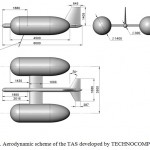 |
Figure 4: Aerodynamic scheme of the TAS developed by TEСHNOСOMPLEKT |
Design aerodynamic characteristics
Let us estimate aerodynamic characteristics of the proposed TAS (hereinafter referred to as scheme 1) and its ability to withstand winds. For comparison, we also consider an aerostat of the classical shape (Fig. 5, hereinafter referred to as scheme 2).
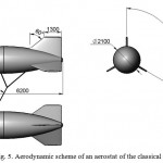 |
Figure 5: Aerodynamic scheme of an aerostat of the classical shape |
The comparison was performed under the following assumptions:
- the volume of the balloons V=11.6 m3 and the take-off mass m=9.5 kg are identical in both schemes;
- the mass of the tether and the aerodynamic force acting on it are ignored;
- in scheme 2 the angle of attack is α = 00, and thus the lift force is produced only by the aerostatic component Y= Ystat
Aerodynamic characteristics of the above schemes were calculated by the numerical method based on solution of Reynolds equations using the ANSYS CFX code. The calculation mesh included 67 million elements for scheme 1 and 23 million elements for scheme 2. The SST turbulence model was used. Compressibility of the air was ignored. The calculations take into account the guidelines presented in [12-15].
The calculations were performed for the flow rate m/s. The values of the aerodynamic forces were scaled to a different rate using the formals

where
q = Pv2/2 is the wind flow pressure;
p = 1.225 kg/m3 is the air density near the ground;
values of Xcalc, Ydyn calc, and qalc correspond to u = 10 m/s.
The results of the calculations are presented in Figs. 6 and 7. As was expected, the wing allows scheme 1 to achieve high aerodynamic lift force (Fig. 6) and aerodynamic quality Kmax ≈ at α = 100 (Fig. 7).
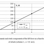 |
Figure 6: Aerodynamic and static components of the lift force as a function of the angle of attack (scheme 1, =10 m/s). |
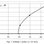 |
Figure 7: Scheme 1 polar (u=10 m/s). |
The plots in Figs. 8 and 9 characterize the behavior of the aircraft affected by wind. Scheme 1 at α = 4.20 (Ydyn≈ 0) can operate only at a wind no stronger than 5 to 7 m/s. At a higher wind speed the aerostat is forced down (at u = 40 m/s the angle φ drops almost to zero). By increasing the angle of attack to α = 100 it is possible to lift the aerostat almost vertically above the tether anchoring place (φ≥800). Beginning with a certain value (u ≈20 m/s at α = 00 and u ≈10 m/s at α = 100), the angle φ stops varying with increasing speed. This is because at a high wind flow pressure q the aerostatic component of the lift force can be ignored, and the angle φ is determined by the speed-independent aerodynamic quality of the aircraft, φ = artg(k) Thus, the limiting wind speed for this scheme is determined only by the strength of the tether and the structure.
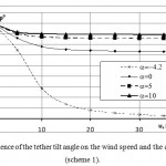 |
Figure 8: Dependence of the tether tilt angle on the wind speed and the angle of attack (scheme 1). |
Scheme 2 cannot withstand the wind, and the angle φ decreases with increasing wind speed (Fig. 9).
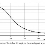 |
Figure 9: Dependence of the tether tilt angle on the wind speed at (schem 2). |
To illustrate, Figs. 10 and 11 show calculated lines of flow on the surface of schemes 1 and 2.
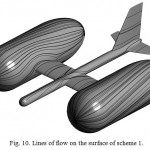 |
Figure 10: Lines of flow on the surface of scheme 1. |
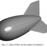 |
Figure 11: Lines of flow on the surface of scheme 2. |
Conclusions
To develop TASs of different volume and for different purposes is a currently important and promising objective. For extending capabilities of small-sized TASs, it is necessary to increase their ability to withstand the wind. A possible solution of this problem is to use the hybrid scheme.
In this paper a design of a small-sized hybrid TAS is described. Its calculated aerodynamic characteristics are compared with a classical aerostat of similar load-lifting capacity.
It is shown that the wind speed is limited for the proposed scheme only by the strength of its tether and structure while the classical aerostat loses altitude as the wind speed increases.
The paper is prepared in the scope of the applied research and development (AR&D) performed under Grant Agreement No. 14.579.21.0082 with the financial support of Ministry of Education and Science of the Russian Federation. The unique AR&D identifier is RFMEFI57914X0082.
References
- Lockheed Martin. Retrieved April 14, 2015, from www.lockheedmartin.com/us/products/lighter-than-air-vehicles.html.
- TCOM L.P. Retrieved April 14, 2015, from http://www.tcomlp.com/aerostat-platforms.
- Augur RosAeroSystems. Retrieved April 14, 2015, from http://rosaerosystems.ru.
- Bendin S. Aerostats will ensure monitoring of US and Israel air borders. Retrieved April 14, 2015, from http://www.pandia.ru/text/77/408/43817.php.
- Parsch A. Tethered Aerostats. Directory of U.S. Military Rockets and Missiles. Appendix 4: Undesignated Vihicles. 2003. Retrieved April 14, 2015, from http://www.designation-systems.net/dusrm/app4/aerostats.html.
- Verba G.E., Shchugarev S. N., Ivchenko B.A., Ponomarev P.A., Talesnikokv M.V. (2012). Current world trends in development of aircraft for security and military purposes. Izvestiya Yuzhnogo Federalnogo Universiteta/Technicheskie Nauki/, 3, 49–58.
- Sokut S. (2003). Aerostats come to help AWACS. Nezavisimoe Voennoe Obozrenie, March 14, 2003.
- Hybrid aircraft. RF Useful Model Patent 109738. Publ. 27.10.2011.
- Tethered aerostat. RF Useful Model Patent 40289. Publ. 10.09.2004.
- Wind-withstanding tethered aerostat. RF Patent 2279994 No. 2004139144/11; appl. 22.12.2004; publ. 20.07.2006.
- Colibris aerostat. Moscow Aviation Insititute. Retrieved April 14, 2015, from http://www.mai.ru/science/dev/index.php?ELEMENT_ID=9897.
- Bosniakov S.M., Akinfiev V.O., Vlasenko V.V., Glazkov S.A., Lysenko A.V., Matyash S.V., Mikhailov S.V. (2006). The methodology of mathematical modeling of flow models in wind tunnels and experience of its practical application. Tekhnika vozdushnogo flota, 5, 1-20.
- Bosniakov S.M., Akinfiev V.O., Vlasenko V.V., Glazkov S.A., Lysenko A.V., Matyash S.V., Mikhailov S.V. (2006). The methodology of mathematical modeling of flow models in wind tunnels and experience of its practical application. Tekhnika vozdushnogo flota, 6, 1-13.
- Tarasenko A.V. (2009). The practical aspects of solving the external aerodynamics of subsonic aircraft under the Euler equations. Tekhnika vozdushnogo flota, 1, 22-44.
- Tarasenko A.V. (2010). The practical aspects of solving the external aerodynamics of subsonic aircraft under the Reynolds equations. Tekhnika vozdushnogo flota, 2, 1-16.

This work is licensed under a Creative Commons Attribution 4.0 International License.


