How to Cite | Publication History | PlumX Article Matrix
Evaluation Criteria Fingers Hardness Electrode MEMS Comb Converters
Boris Georgievich Konoplev, Igor Evgenievich Lysenko, Olga Aleksandrovna Ezhova
Southern Federal University, Russia, 344006, Rostov-on-Don, Bolshaia Sadovaua st., 105/42
DOI : http://dx.doi.org/10.13005/bbra/1910
ABSTRACT: The assessment criterion of the rigidity of comb electrodes fingers of the microelectromechanical converters is developed. The assessment criterion allows to estimate the maximum electrodes fingers length to decrease approach probability of snap-down effect. The modeling results have been analyzed. The estimations of the maximum length of electrodes fingers are obtained. The estimates depend on length of electrodes fingers overlapping and applied voltage. The dependences of the maximum length of comb electrodes fingers on length of their overlapping and applied voltage are showed. Since all of the electromechanical converters are reversible, i.e. the converters can work as electrostatic actuators, as well as capacitive displacement transducers. The criteria allowed to define these invertibility condition can be obtained from the equilibrium equations of sensitive elements of micromechanical devices. The proposed assessment criterion of the maximum length of combs electrodes fingers can be used to design micromechanical devices.
KEYWORDS: microelectromechanical systems (MEMS); electromechanical converters; model; modeling
Download this article as:| Copy the following to cite this article: Konoplev B. G, Lysenko I. E, Ezhova O. A. Evaluation Criteria Fingers Hardness Electrode MEMS Comb Converters. Biosci Biotechnol Res Asia 2015;12(3) |
| Copy the following to cite this URL: Konoplev B. G, Lysenko I. E, Ezhova O. A. Evaluation Criteria Fingers Hardness Electrode MEMS Comb Converters. Biosci Biotechnol Res Asia 2015;12(3). Available from: https://www.biotech-asia.org/?p=3594> |
Introduction
Microsystems technology emerged in the mid-eighties of last century at the junction of electronics, mechanics and optics. The microsystems technology remains one of the most dynamically developing scientific and technical sphere. Microelectromechanical systems (MEMS) are based on microsystems technology components. MEMS are devices with integrated in or on a solid body electronic and micromechanical structures and are a class of miniature devices or systems fabricated by micromachining processes. MEMS devices have critical dimensions in the range 100 – 1000 µm (or 1 mm). MEMS technology is a precursor to the relatively more popular field of Nanotechnology, which refers to science and technology below 100 nm down to the atomic scale [1,2].
MEMS proved to be a revolutionary technology in various fields of the physical spheres. Pressure sensors, Accelerometers, and Gyroscopes are from mechanical domain of physics, Inkjet nozzles is from microfluidics, Microphone is from acoustics, Switches and Resonators are from RF MEMS and Micromirrors are from optical MEMS. MEMS technology has demonstrated unique solutions in various spheres delivering innovative products in chemical, biological and medical domains. Demand of MEMS has been high into various consumer industry such as electronics, home appliances, automotive industry, aerospace industry, biomedical industry, recreation and sports [1-3].
Market of microsystem technology is growing extensively. The microtechnology industry has been more eager to invest with every year. Almost a third of participating companies have invested more in 2015 than in the year before [1-3]..
The automotive industry has recently experienced a growth around the world. For the microtechnology,too, this market has become more important than in previous three years.Automotive technology is the major target market for 11% of companies. There are strong reasons for comeback of the automotive industry in the list of major target markets, such as: a growing need for intelligent systems, e.g. driver assistance systems, the connectivity of cars with entertainment and information services, and the development of alternative drive concepts, such as electric or hydrogen engines [1-4].
The global automotive MEMS sensor market was valued at $2,600.5 million in 2014, and it is expected to grow at 6.0%, during the period 2015-2020, according to P and S Market Research. The governments of European countries regulation towards passenger safety and environment has become more stringent in recent years, and therefore automotive industries are forced to implement latest sensor based automotive safety features, such as Electronic stability control (ESC), Tire Pressure Monitoring Systems (TPMS), Anti-lock braking system (ABS), Advanced Driver Assistance Systems (ADAS).The development in the areas of vehicle to infrastructure (V2I) and vehicle to vehicle communication (V2C) is providing new market opportunity for the low cost wireless MEMS sensors used in the automotive technology. The advance in the IC fabrication technology has reduced cost effective fabrication process of automotive MEMS. The modern IC fabrication technology provides monolithic integration of micro electromechanical structure, with controlling and driving electronics [2-5].
Wearable electronics is other promising market where MEMS technologies are in widespread use. Some analysts estimate that the wearable industry will reach $265 million units by 2020. Wearable technology is expected to be part of the IoT revolution, bringing useful information directly to the user in a more natural way than with traditional devices. Three device types are expected to successfully reach the market: smartwatch, smart glasses/HUD, and smart clothing[3,7].
The MEMS sensors industry has acquired from the smartphone market a strong experience in inertial sensors, microphones, and environmental sensors. So the MEMS developers have changed the boundaries of performance and size. Sensors are now so small, reliable, and accurate that can be included in a pocket-sized device of only 9cm3. These sensors are the ones that can be found in wearable devices until 2018[2-5].
Today, there is a popular term “BioMEMS” using to refer to the science and technology of microdevices fabricated by micromachining for medical applications or biological studies. Also BioMEMS may include any electrical or mechanical functions. Areas, where Application of BioMEMS is used, include microsurgical tools, biomedical transducers, microfluidics, medical implants and tissue engineering.
In 2012 the global BioMEMS market costed about $1.9 billion. Now it is expected to almost triple in size to $6.6 billion in 2018 [1,2].
Various devices of microsystem technology have become increasingly visible in the healthcare market, because the microsystem technology serve as solutions adapted to the requirements of various applications. The usefulness of microsystem devices is incontestable: they improve medical device performance for the patient; and they offer competitive advantages to system manufacturers. For example, the introduction of acceleration sensor in pacemakers has reversed the treatment of cardiac diseases. The Microsystem technologies market for Healthcare applications looks promising, and should reach $6.6 billion by 2018. Yole Développement has followed this market’s innovations[1-5].
In the 1980s the first MEMS devices were used in the biomedical industry. The devices were reusable blood pressure sensors. MEMS pressure sensors have the largest class of applications in medical industry such as disposable blood pressure, intraocular pressure, intracranial pressure, intrauterine pressure and angioplasty. CardioMEMS, Freescale semiconductors, Measurement Specialties, Omron, Sensimed AG and Silicon Microstructures are some manufacturers of MEMS pressure sensors for biological and medical applications [1-4].
MEMS sensors of linear acceleration are used in defibrillators and pacemakers. Patients exhibit unusually fast or chaotic heart beats, thus are at a high risk of cardiac arrest. An implantable defibrillator with MEMS sensor restores a normal heart rhythm by providing electrical shocks to the heart during abnormal conditions. MEMS inertial sensors of angular velocity and linear acceleration were employed to develop one of the most unique wheelchairs, the iBOTTM Mobility system. A combination of multiple inertial sensors integrated in this system enables the user to operate the wheelchair and lift to a standing height balancing on two wheels without help of other people. This allows the wheelchair user to interact with others face-to-face. The iBOTTM system was developed by D. Kamen in a partnership between DEK and Johnson and Johnson’s Independence Technology division. Another related example is the Segway PT, a two-wheeled, self-balancing, battery-powered electric vehicle [1-5].
The main devices included by the term BioMEMS are: pressure sensors, Silicon microphones, linear acceleration sensors, angle velocity sensors, microfluidic chips, microdispensers for drug delivery, flow meters, infrared temperature sensors, optical MEMS and image sensors[2-6].
MEMS integration with optical components allows to allocate a separate class of components of the microsystems. This class is called microopticoelectromechanical systems. Basic elements of these systems are microelectromechanical converters including electrostatic actuators and capacitive displacement transducer [2-6].
Designing of electrostatic actuators and capacitive displacement transducer of micromechanical devices it is necessary to consider a number of effects that can cause snap-down effect of movable and fixed structures [7-9].
Problem statement
Microelectromechanical systems is a technology that in general form can be defined as miniaturized mechanical, electro-mechanical and optical elements : devices and structures, that are made using the techniques of microfabrication. The critical physical dimensions of MEMS devices can vary from well below one micron on the lower end of the dimensional spectrum, all the way to millimeters. The types of MEMS devices can vary from simple structures having no moving elements to extremely complex electroopticomechanical systems with multiple moving elements under the control of integrated microelectronics. The one main criterion of MEMS is that there are some elements having some sort of mechanical functionality whether or not these elements can move. While the functional elements of MEMS are miniaturized structures, sensors, actuators the most most interesting elements are the microsensors and microactuators. Microsensors, microactuators are in common categorized as “transducers”, being defined as devices that convert energy from one form to another. In the case of microsensors, the devices converts a measured mechanical signal into an electrical signal [4-10].
Past several decades have showed that MEMS researchers and developers have demonstrated an extremely large number of microsensors for almost every possible sensing modality including temperature, pressure, inertial forces, chemical species, magnetic fields. Surprisingly, many of these micromachined sensors have demonstrated performances exceeding those of their macroscale devices. MEMS research and development community has demonstrated a number of microactuators including: microvalves for control of gas and liquid flows; optical switches and mirrors to redirect or modulate light beams; independently controlled micromirror arrays for displays, microresonators for a number of different applications, micropumps to develop positive fluid pressures, as well as many others. Even though these microactuators are extremely small, they frequently can cause effects at the macroscale level; these tiny actuators can perform mechanical feats larger than their size would imply [3-6].
As stated in the principles of the micromechanical devices [9-11] the reciprocating or rotary motion of movable elements is necessary for correct work. However, as shown in Figure 1, the electric field arises in cause the deflection voltage is applied between the movable and fixed electrodes of electromechanical converters. The electric field leads to a deviation of movable electrodes is not only along the y-axis, but also along the x- and z-axis [12-14].
The movable and fixed electrodes of electromechanical converters are manufactured in one structural layer, therefore it is possible to select the type of technological errors such as drift gap between the fingers. [12]. The specified technological error leads to oscillations of moving elements under the action of the resulting electrostatic forces directed along the x-axis. These oscillations are caused by tension/compression of beams of an elastic suspension of movable electrodes.
As shown in works [10-13] the oscillation amplitude is tiny percent from the gap size between electrodes fingers and affects to emergence of snap-down effect slightly.
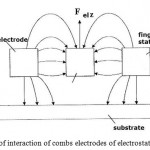 |
Figure 1: Scheme of interaction of combs electrodes of electrostatic actuator |
Besides, the electric field along x-axis would capable to cause snap-down effect of combs electrodes fingers of electromechanical converters, if fingers rigidity is insufficient, as shown in figure 2 [12].
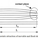 |
Figure 2: Electrostatic attraction of movable and fixed electrodes |
Therefore designing the topology of electrostatic actuators and capacitive displacement transducers of micromechanical devices, it is necessary to consider the impact of this component of the electric field and introduce the criterion stiffness of the fingers of movable and fixed electrodes of electromechanical converters.
Results
Based on expressions for calculation rigidity of cantilever beams and of electrostatic forces, generated planar electrostatic actuators [6, 13] the criterion of the maximum length of electrodes fingers of electromechanical converters are obtained:

where – width of the comb electrodes fingers; – length of overlapping of the comb electrodes fingers; – distance between fingers of combs of movable and fixed electrodes; – Young’s modulus; ε – relative dielectric permittivity of an air-gap; – an electric constant; U– voltage.
Figure 3-6 show the dependences of the maximum length of comb electrodes fingers on length of their overlapping and applied voltage.
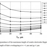 |
Figure 3: Dependence of the maximum length of combs electrodes fingers on length of their overlapping at w =1 μm and g0=1 μm |
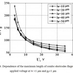 |
Figure 4: Dependence of the maximum length of combs electrodes fingers on applied voltage at w =1 μm and g0=1 μm |
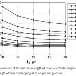 |
Figure 5: Dependence of the maximum length of combs electrodes fingers on length of their overlapping at w =2 μm and g0=2 μm |
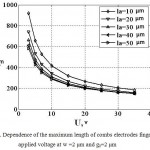 |
Figure 6: Dependence of the maximum length of combs electrodes fingers on applied voltage at w =2 μm and g0=2 μm |
The electrostatic actuators produce the electric field. The influence of the electric field along the z-axis causes levitation effect of moving structures of micromechanical gyroscope and, consequently, the existence of the quadrature error. The substrate is grounded to eliminate the levitation effect. As result there is asymmetric electric field. The field acts in the upper part of electrostatic actuators and can not cause oscillations with an amplitude affecting the quadrature error significantly. Additional fixed electrodes can be applied to eliminate the asymmetric electric field. The additional electrodes can be locate over comb structures movable and fixed electrodes [12].
Conclusion
Micromechanical systems are used widely in modern technical devices of different applications: from the specialized products of aerospace systems and defensive systems to home appliances, such as phones and game platforms of new generation, medical applications, biological researches. Since all of the electromechanical converters are reversible [9, 10], i.e. the converters can work as electrostatic actuators, as well as capacitive displacement transducers. If certain conditions occurs, the capacitive displacement transducers will start to work like electrostatic actuators. The criteria allowed to define these invertibility condition can be obtained from the equilibrium equations of sensitive elements of micromechanical devices.
The proposed assessment criterion of the maximum length of combs electrodes fingers can be used to design micromechanical devices.
Acknowledgments
Work is executed with financial support of the Ministry of Education and Science of the Russian Federation (project no. 14.575.21.0045, RFMEFI57514X0045).
References
- Elwenspoek, M. and R. Wiegerink, 2005. Silicon micro accelerometers. Mechanical microsensors, pp: 230-236.
- Ramadoss, R., 2013. MEMS devices for biomedical applications. Solid State Technology, 10: 10-13.
- Bourne, M., 2007. A consumer’s guide to MEMS and nanotechnology, Bourne research LLC, 1st edition.
- Xie, H. and G.K. Fedder, 2003. Integrated microelectromechanical gyroscopes. Journal of aerospace engineering, 4: 65-75.
- Vigevani, G., 2011. MEMS Aluminum Nitride Technology for Inertial Sensors, Ph.D. Dissertation, University of California, Berkeley, CA.
- Sung, W.T., T. Kang and J.G. Lee, 2008. Controller Design of a MEMS Gyro-Accelerometer with a Single Proof Mass. International Journal of Control, Automation, and Systems (issue 6), pp: 873-883.
- Verner, V.D., P.P. Mal’cev, A.A. Reznev, N. Saurov 2008. Modern tendencies of development of microsystem technique. Journal of Nano- and microsystem technique, 8: 2-6.
- Verner, V.D., A.A. Ivanov, N.G. Kolomenskaja, V.V. Luchinin, P.P. Mal’cev, I.V. Popova, A.N. Saurov, V.A. Telec, 2007. Elements of microsystem technique – main definitions and terms. Journal of Nano- and microsystem technique, 12: 2-5.
- Gridchin, V.A., V.P. Dragunov, 2004. Microsystem physics. Novosibirsk NGTU publishing house, pp. 416.
- Raspopov, V.Ja., 2007. Micromachanical devices. Mashinostroenie, pp. 400.
- Lysenko, I.E., 2005. Design of sensor and actuator elements of microsystem technique. Taganrog: TRTU publishing house, pp.103.
- Palaniapan, M., 2002. Integrated surface micromachined frame microgyroscopes. University of California, Berkeley, pp. 168.
- Pristupchik N., Konoplev B., Kulikova I., Klunnikova Y., Lysenko I., 2015. Quantum Tunneling in Mesoscopic Electromechanical Transducers. Modern Applied Science, 9: 20-29.
- Lysenko I., 2013. Modeling of the micromachined angular rate and linear acceleration sensors LL-type with redirect of drive and sense axis. World Applied Sciences Journal, 27: 759-762.

This work is licensed under a Creative Commons Attribution 4.0 International License.


