How to Cite | Publication History | PlumX Article Matrix
Analysis of Magnetic Endoscopic Capsule Movement in Human Digestive Tract
Evgeny Zharikov and Anastasia Tolstaya
National Research Nuclear University MEPhI (Moscow Engineering Physics Institute), Kashirskoe highway 31, 115409, Moscow, Russian Federation.
Corresponding Author E-mail: tolstaya.a@inbox.ru
DOI : http://dx.doi.org/10.13005/bbra/2345
ABSTRACT: This article deals with the security issue of the endoscopic capsule control and movement in human body using external magnetic field. The authors describe four different variants of power connection to the magnetic coil: direct connection with the source output on resistance; direct connection with the source output in the opposite phase; oscillating circuit in critical mode; oscillation circuit with the output on resistance. Their advantages and disadvantages are considered. The analysis of the capsule movement and its control characteristics for each of the listed options of the magnetic coils powering is presented.
KEYWORDS: magnetic coils powering; security of endoscopic capsule movement; movement calculation
Download this article as:| Copy the following to cite this article: Zharikov E, Tolstaya A. Analysis of Magnetic Endoscopic Capsule Movement in Human Digestive Tract. Biosci Biotech Res Asia 2016;13(4). |
| Copy the following to cite this URL: Zharikov E, Tolstaya A. Analysis of Magnetic Endoscopic Capsule Movement in Human Digestive Tract. Biosci Biotech Res Asia 2016;13(4). Available from: https://www.biotech-asia.org/?p=16621 |
Introduction
Recent advances in the wireless capsule endoscopy can significantly improve the efficiency of the gastrointestinal tract (GIT) examination, improve the quality of images recorded by the capsule and the software performance recognizing pathology of the digestive tract [1-2], avoid the data loss [3], improve the capsule manageability [4-6], etc.
Many research papers are devoted to the issue of development of systems that control the wireless capsule by the magnetic field [7-10]. The coils generate an external magnetic field under the influence of which the endoscopic capsule with an integrated magnet moves through the digestive tract, retains, turns, stops, etc. All this provides a more detailed examination of the gastrointestinal tract.
One of the key requirements for the control of the capsule movement is to ensure patient safety. This requirement is impossible to comply with without constant monitoring of accelerations and displacements of the device under the influence of the external magnetic field. With each capsule shift the amplitude of the magnetic field and, consequently, the maximum value of the currents in the coils of the magnetic system is determined by the operator actions. Thus, to ensure the safety of movements it is necessary to control the profile of the currents input-output in the coils and its duration. Moreover, to select the current pulse shape it is necessary to simulate the capsule movements by the force of the magnetic field created by it and ensure their safety.
Given these features of the magnetic capsule control system for the “Landish” capsule endoscopic complex the movements of the capsule in the human digestive tract was calculated to ensure the full safety of the procedure.
Modeling capsule shifts
The capsule shift along a given direction regardless the rotation is described by the equation:
![]()
where a is the mass of the capsule with a magnet in it, b is the coefficient of proportionality of the drag from the Stokes` law [11] (which describes in detail the case of cylindrical capsule with spherical ends):
![]()
where ν is the dynamic viscosity of the medium; c is the friction force.
To simplify the reasoning the friction force is taken as a constant proportional with the coefficient μ to the capsule weight minus the Archimedes` force. The formula (1) becomes correct only under the condition that f(t)≥c, where f(t) is the force exerted on the capsule by the external magnetic field. Due to the additive property of the magnetic field, this force may be represented as f(t)=I(t)F, where I(t) is the current in the magnetic coils, F is the proportionality coefficient chosen in each case so that the maximum obtained force f(t) is equal to the value requested by the operator:
![]()
Upon further consideration of the capsule movements, the requested force is assumed to be 0.5 N, which corresponds to the most dangerous case.
The solution of the equation (1) will look different depending on the type of the dependence I(t). Therefore, to solve the problem of capsule moving it is necessary to consider the options for the coils powering.
Direct connection with the source output on resistance
One of the easiest ways of power supply is to connect the current to the coil directly followed by the closure on resistance to transfer the accumulated magnetic energy into heat. The diagram of this embodiment is shown in Figure 1.
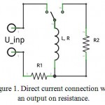 |
Figure 1: Direct current connection with an output on resistance.
Click here to View figure |
The typical form of the current profile for this scheme, shown in Figure 2, consists of two main parts: current input and output on the coil.
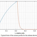 |
Figure 2: Typical form of the current profile for the scheme shown in Figure 1.
Click here to View figure |
First, the current is supplied in the coil. The function f(t), corresponding to the transition process without taking into account the effect of the mutual inductances is given by:

where TL is the resistor-inductor (RL) circuit time constant defined as:

The appropriate to (2) solution of the equation (1) is:

where k1 and k2 are the constants determined from the initial conditions.
The function (3) describes the capsule movement before the time t1 determined by the relation:

where is the current required to achieve the force
![]()
and I is a steady-state current produced by the source (i.e. the current reached in the circuit after the transient). The value I is calculated as:

From (4) it is possible to find the required time t1:

At time point t1 the output resistance R2 is connected to the magnetic coil and the power supply is disconnected. This leads to the current output from the coil and the dissipation of the accumulated energy in the magnetic field on the active resistance. The corresponding function f(t) is as follows:

where TL is the new time constant equal to:

The function describing the capsule movement on the current output stage is:

where k1 and k2 are the constants determined from the initial conditions.
Direct connection with the source output in the opposite phase
The second embodiment of the power supply scheme shown in Figure 3 on the first phase works similarly to the embodiment shown in Figure 1, but then the polarity of the power source switches and it begins to operate in the opposite phase speeding up the current output from the coil.
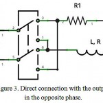 |
Figure 3: Direct connection with the output in the opposite phase.
Click here to View figure |
The advantage of this approach is that after reaching the zero current it is possible to create the opposite field, which will slow down and stop the capsule movement. Thus, due to the characteristics of the circuit transient the integral
![]()
of the current in the coils, which is proportional to the forces exerted on the capsule from the magnetic field, remains positive even if Imin=-Imax (Figure 4). Therefore, in most typical for digestive tract mediums with low viscosity during the current input in the opposite phase the magnetic field is not able to move the capsule in the opposite direction, but only retards it greatly reducing the danger of the GIT damaging.
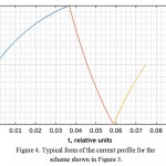 |
Figure 4: Typical form of the current profile for the scheme shown in Figure 3.
Click here to View figure |
For this coils power scheme the initial stage of the current input in the coil is similar to that considered for the previous scheme, and by the time t1 defined by (5), the function that describes the capsule movement corresponds to the formula (3) using the time constant:

In the next phase (source switching in the opposite phase), f(t) is:

and the displacement function is:

where k1 and k2 are the constants determined from the initial conditions.
Providing Imin=-Imax the ending of this phase of the current pulse occurs at time:

where is the steady-state current when the source is in the opposite phase.
At the final stage of the current pulse, there is a current return to zero in the coil by direct voltage supply. This force exerted from the magnetic field is given by:

Then the solution of the equation (1) can be written as:

where k1 and k2 are the constants determined from the initial conditions.
Oscillating circuit in critical mode
In addition to the direct connection of the power source to the coil, the capacitor can be used for the energy storage with the subsequent discharge at the winding. The relevant connection diagram is shown in Figure 5.
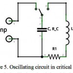 |
Figure 5: Oscillating circuit in critical mode
Click here to View figure |
There are three possible modes of the oscillatory circuit operation:

damped oscillations. For the endoscopic capsule control system, this mode is inapplicable primarily due to its poor predictability in terms of the inductive coupling of each of the coil with the neighboring one as well as due to the low energy efficiency of the capsule movement occurring because of the caused by the current fluctuations alternating accelerations and decelerations. Furthermore, this mode will be too sensitive to the errors of the capsule position determination that will lead to an unnecessary risk of the GIT injury.
![]()
aperiodic fluctuations. This mode is not suitable for the magnetic control of object since it has a low energy efficiency and a low rate of current decay, leading to the risk of uncontrolled acceleration of the capsule.
![]()
critical mode. This mode is optimal for the capsule control, as it has the most rapid current decay without the oscillation and an acceptable current amplitude. It also has the highest energy efficiency of movement comparing with above considered modes of the RLC (resistor, inductor, capacitor) circuit. The current profile typical for this mode is shown in Figure 6.
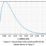 |
Figure 6: Typical form of the current profile for the scheme shown in Figure 5.
Click here to View figure |
When using the oscillation circuit the current profile is described by the equation
![]()
that for the initial conditions of the endoscopic capsule position control system

where UC is the voltage on the capacitor before the key closure) takes the form:

Here

The maximum of the function (7) falls on the moment
![]()
and the peak current is equal to

from which we can determine the required voltage on the capacitor plates on the basis of the desired value of the maximum current:

The capacitance of the capacitor is defined from the condition of a critical mode of the circuit as:

In case of the oscillation circuit in a critical mode the function of the force exerting on the capsule looks like:
![]()
The function of the capsule position is as follows:

where k1 and k2 are the constants determined from the initial conditions.
Oscillation circuit with the output on resistance
From the previous scheme, the embodiment shown in Figure 7 differs by the provided opportunity to turn off the magnetic coil from the capacitor by closing it on resistance. As it can be seen from the typical current profile in Figure 8, it is possible to quickly bring the current out from the coil limiting the capsule movement and reducing the risk of damaging the patient. Thus, before reaching the peak current at a moment
![]()
(in case of a critical mode of the oscillatory circuit) the capsule movement is described by the function (8) and then by the function (6).
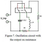 |
Figure 7: Oscillation circuit with the output on resistance
Click here to View figure |
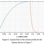 |
Figure 8: Typical form of the current profile for the scheme shown in Figure 7.
Click here to View figure |
Analysis of the results
For further analysis of the capsule behavior and control characteristics for each of the listed options of powering the magnetic coil, we created a software (Figure 9) with a graphical interface, which plots the movement path and the capsule speed based on the input parameters of the system according to the above functions.
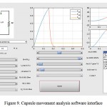 |
Figure 9: Capsule movement analysis software interface
Click here to View figure |
The main purpose of the analysis of the capsule movement patterns under the influence of the external magnetic field is the search of the modes, in which the capsule displacement with a maximum design force does not exceed 1.5 cm. This corresponds to the minimum diameter of the human small intestine minus the diameter of the endoscopic capsule and is taken as the safe shift. Furthermore, at the end of such a shift the capsule speed should not exceed 0.1 m/s to prevent damage to body tissues.
Direct source connection
First, we should define the basic capsule movement dependences on the technical parameters of the system. The analyzed parameter varies under the permanence of other controlled variables. The environment conditions for all comparisons are considered as the glycerol at a room temperature.
The most important are the dependences on the physical parameters of the coil: winding type and maximum current density therein. The example of the direct connection with the current output on resistor shows that the bigger is the cross-section of the winding wire, the faster stops the capsule that exerted the desired force. This dependence is associated with a decrease in the number of turns of the wire required for a given magnetomotive force with its growing cross-section. This in turn leads to a decrease in the coil inductance and, therefore, to the acceleration of current input and output. The comparison of the capsule displacements with different cross-sections of the winding wire is shown in Figure 10. It is clear that the decrease in movement is strongly not linear, and becomes significant only with the cross-sections of the wire over 250 mm2.
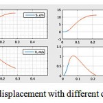 |
Figure 10: The capsule speed and displacement with different cross-sections of the winding wire. From left to right: 20, 90, 225, 600 mm2.
Click here to View figure |
Similarly, the capsule displacement decreases due to the decrease of the coil inductance with the increase of the current density, but in this case, the dependence is closer to linear. The changing in the capsule movement with the changing in the current density in the coil is shown in Figure 11.
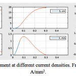 |
Figure 11: The capsule movement at different current densities. From left to right: 8, 25 and 40 A/mm2.
Click here to View figure |
Then we analyze the dependence of the movement on the output resistance. It is obvious that the higher is the resistance, the lower is the characteristic time of the current output, and hence the capsule earlier becomes to accelerate and starts to stop. The calculations showed that when the value of the output resistance is more than a certain threshold (about 0.2 Ohm) the current output no longer has a significant influence on the final movement of the capsule, and the output voltage remains within tolerance.
One of the basic control parameters in the setup is an active resistance value, through which the coils are charged from the source. The higher is this resistance, the faster the current in the coil reaches a required value and the safer becomes the movement of the magnetic capsule. An example of such a dependence is shown in Figure 12. For the used system parameters even at the resistance R1 = 0.2 Ohm the capsule moving becomes safe. The disadvantage of the resistance increase is the increase in the required power supply for the coils, as the supplied energy begins to dissipate on the additional resistance.
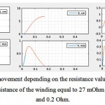 |
Figure 12: The capsule movement depending on the resistance value R1. From left to right: 0 mOhm (only the active resistance of the winding equal to 27 mOhm is in the circuit) 40 mOhm and 0.2 Ohm.
Click here to View figure |
The remaining for the analysis parameter in case of the direct connection of the power supply is the time of the coil cut off from the source (the time of the power phase change). This parameter should be considered in a conjunction with the dipole resistance, selecting the value of R1 to maintain the final movement. The basic analyzing parameter is the required power source. A typical result of such an analysis of the two power supply options is shown in Table 1 (the final movement is maintained at 1.5 cm). It can be seen that for the version with the current output on resistance the optimal value
![]()
and it provides the minimum requirement power source. At the same time for the sources in the opposition phase, the minimum is in the interval
![]()
The embodiment with the source output in the opposite phase is almost twice more efficient in terms of energy consumption.
Table 1: Comparison of the required pulse power of the source depending on the system parameters.
| Output on resistance | Output in the opposite phase | ||
| 80 mOhm | 1280 kW | 0 mOhm | shift < 1.5 sm |
| 110 mOhm | 600 kW | 22 mOhm | 230 kW |
| 140 mOhm | 510 kW | 49 mOhm | 230 kW |
| 180 mOhm | 500 kW | 78 mOhm | 250 kW |
| 220 mOhm | 525 kW | 105 mOhm | 280 kW |
| 265 mOhm | 580 kW | 138 mOhm | 330 kW |
| 350 mOhm | 710 kW | 217 mOhm | 460 kW |
Oscillating circuit
The dependences of the capsule displacement on the cross-section of the winding wire and the maximum current density for the oscillation circuit are similar to the dependences for direct source connection to the coil. The higher the current density and the bigger the cross-section, the smaller the coil inductance, and as a result, the faster terminates the force accelerating the capsule.
The main control parameter in this case is the RLC-circuit resistance (as for the direct connection). The example of the configuration avoiding the harmful for the GIT movements is shown in Figure 13.
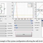 |
Figure 13: The example of the system configuration allowing the safe level of capsule shift.
Click here to View figure |
The analysis showed that practically throughout the entire range of possible parameters the required values of the capacitor capacitance and voltage allow to implement these schemes by assembling a capacitor from the commercially mass-produced electrolytic capacitors. However, in this scheme, all the energy stored in the capacitor is dissipated into the heat at one shift of the capsule, and then you need to re-charge it. At the same time, fast charging will require the power supplies comparable with the sources needed for the direct current input in the coil. The charging from a cheaper and less powerful source will take a lot of time, which will significantly reduce the performance and limit the possibility of installing the magnetic manipulation of the endoscopic capsule.
Determination of design parameters
As it was said above, to reduce the shift it is desirable to select the bigger wire cross-section. At the same time, the industry produces ready-winding wires has a maximum cross-section of 60 mm2 and the use of a larger cross-section is not desirable as it would require the wire manufacturing on request. In addition, the winding of the wire with a big cross-section on the coils of a diameter adopted in our design becomes a technical challenge. These factors lead to a multiple rise in the production costs of the experimental setup. Therefore, in the final design as the winding wire we use a standard ПСДКТ with a wire maximum manufactured cross-section.
Another way to increase the efficiency of the setup performance according to the analysis is to increase of the calculated current density. The limitation here is the thermal resistance of the device.
The energy released in the magnetic coil is calculated as:
![]()
where R is the coil resistance, Imax is the current on the winding wire, D is the duty cycle, and k is the coefficient that takes into account the effect of the pulse shape.

and, considering the pulse shape slightly different from the triangle, we obtain k = 1/3.
Having the permissible temperature drop equal to ΔT = 30K , and neglecting the heat exchange of the coil with the environment during its operation (which is true due to the high heat capacity of the copper and the low thermal conductivity and heat-insulating varnishes coating the cooper in the coil), we can calculate the allowable time t:

where с is the winding the heat capacity (electrical copper), m is the coil weight.
Substituting (9) into (10) and expressing a part of the factors in terms of the current density j, copper resistivity r, winding wire cross-sectional area S, length l and copper density ρ, we obtain:

The values substitution for D=1 (the mode required to demonstrate the capabilities and limitations of the selected control method) gives the results shown in Table 2.
Table 2: Permissible operating time at D=1.
| j, А/mm2 | 8 | 10 | 15 | 20 | 25 | 30 | 35 |
| t | 4.5 min | 2.9 min | 1.3 min | 43 s | 28 s | 19 s | 14 s |
The final design current density of the experimental setup is chosen to be 25 A/mm2, which allow to carry out a 20-second experimental launches of the setup (including the wire resistance increasing while heating), as well as leaves reserves for testing operation at high fields and accordingly large currents.
Let us calculate the coils resistance corresponding to the selected parameters. The resistance is defined by the formula where ρ is electrical resistivity in Ohm*m, l is the conductor length, S is the conductor cross-sectional area. In this case = 0.0175 Ohm*mm2/m, S=10.6*5=53 mm2, l=2π*(300+44/2)*40=80 m. Thus, the resistance of each of the windings is R=0.0116 Ohm.
Conclusion
In this paper we are looking for the most secure option, which gives the ability to effectively control the capsule (i.e. its position and velocity) and secure in terms of working with an electromagnetic energy (current, which is put in and out from the coils).
This article describes four options for connecting the source to power the magnetic coils of the capsule endoscopic complex:
direct connection with the source output on resistance;
direct connection with the source output in the opposite phase;
oscillating circuit in critical mode;
oscillation circuit with the output on resistance.
For each method of connection, the advantages and disadvantages are considered.
Depending on the design of the power supplies, we will choose one of the options. The contents of this article will be used for further development of the control system of the “Landish” magnetic capsule endoscopic complex.
Acknowledgement
The publication is prepared in accordance with the scientific research under the Agreement between “Mobile informatics” (LLC) and Ministry of Education and Science of the Russian Federation № 14.579.21.0053 от 23.09.2014. Unique project identification number RFMEFI57914X0053.
References
- Kukushkin Alexander, Mikhaylov Dmitry, Ivanova Ekaterina, Fedorov Evgeny, Zhukov Igor, Semenov Sergey, Tolstaya Anastasia, Muleys Rami, Starikovski Andrey. Recognition of Hemorrhage in the Images of Wireless Capsule Endoscopy. The 16th IEEE Mediterranean Electrotechnical Conference MELECON 2012. Pages: 899-902.
- Mikhaylov Dmitry, Zhukov Igor, Konev Vladimir, Starikovskiy Andrey, Khabibullin Timur, Tolstaya Anastasia, Kukushkin Alexander. Review of features and metafeatures allowing recognition of abnormalities in the images of GIT. 17th IEEE Mediterranean Electrotechnical Conference (MELECON), 2014. 13-16 April 2014. Pages: 231 – 235.
CrossRef - Mikhaylov D.M., Averin A.V., Starikovskiy A.V., Konev V.N. Designing a planar antenna for reading device of the capsule endoscopic complex. Biosciences Biotechnology Research Asia, December 2014. Vol. 11(3), p. 1453-1458.
CrossRef - Dmitry Mikhaylov, Timur Khabibullin, Igor Zhukov, Andrey Starikovskiy, Landish Gubaydulina, Natalya Romanchuk and Vladimir Konev. Development of Retention System of the Autonomous Endoscopic Capsule and Its Functionalities. BIODEVICES 2014. Proceedings of the International Conference on Biomedical Electronics and Devices. ESEO, Angers, Loire Valley, France. 3 – 6 March, 2014. Pages 77-84
- Khabibullin Timur, Anpilogov Artem, Shayakov Askar, Konev Vladimir, Lebedev Grigoriy, Tolstaya Anastasia and Shinkarenko Anton. Magnetically based hardware-software complex for wireless endoscope capsule control. Biosciences Biotechnology Research Asia, Volume No. 12 Issue No.: 2, 2015. Pages: 1273-1280.
- Lebedev G.N., Zharikov E.S., Tolstaya A.M., Tolstaya P.M. Choosing a retention method to control the endoscopic capsule by a magnetic field. Biosciences Biotechnology Research Asia, Vol. 13(2), 2016. Pages: 1265-1278.
CrossRef - Chen, X. Wang and Y. Lou. Modeling and simulation of magnet-guided active endoscopic capsules manipulated by robots. Information and Automation (ICIA), 2014 IEEE International Conference on, Hailar, 2014, pp. 881-886.
- М. Mikhaylov, Т.R. Khabibullin, G.N. Lebedev, А.F. Shayako, А.О. Pasko, I.G. Bulychev, P.M. Tolstaya. Determining of Temperature Working Mode for Solenoids of Magnetic System Prototype for Wireless Endoscopic Capsule. International Journal of Tomography and Simulation, Volume 29, Issue Number 3, 2016. Pages: 19-31.
- Lucarini, G., Mura, M., Ciuti, G., Rizzo, R., Menciassi, A. Electromagnetic control system for capsule navigation: Novel concept for magnetic capsule maneuvering and preliminary study. Journal of Medical and Biological Engineering, Volume 35, Issue 4, 2015, Pages 428-436.
CrossRef - Lucarini, G., Ciuti, G., Mura, M., Rizzo, R., Menciassi, A. A new concept for magnetic capsule colonoscopy based on an electromagnetic system. View at Publisher. International Journal of Advanced Robotic Systems, Volume 12, 26 March 2015.
CrossRef - Lojcjanskij L. G. Mehanika zhidkosti i gaza, 3 izd., M., 1970. 92.

This work is licensed under a Creative Commons Attribution 4.0 International License.


