How to Cite | Publication History | PlumX Article Matrix
Skeletal tracing of impacted and erupted mandibular third molar areas using panoramic radiographs
Hesham Khalil
Department of Oral and Maxillofacial Surgery, College of Dentistry, King Saud University, Riyadh Saudi Arabia.
Corresponding Author E-mail : hkhalil@ksu.edu.sa
ABSTRACT: The aim of the study is to determine whether there are statistically significant differences in gonial angles, ramus body relation, and mesiodistal crown width at the areas of impacted and erupted mandibular third molars. Materials and Methods The study sample consisted of 432 panoramic radiographs selected from the Oral and Maxillofacial Surgery Department, College of Dentistry, King Saud University, Riyadh, Saudi Arabia. Each radiograph had a full complement of mandibular teeth with unilateral impacted lower third molar. Panoramic radiographs were taken and analyzed to compare the difference between erupted and impacted third molar areas. Results The results showed that there is statistically significant change in ramus body relations between the areas of impacted and erupted mandibular third molars, while there is no statistically significant change in gonial angles and mesiodistal crown width. Conclusion Sites with impacted mandibular third molars area exhibit shorter mandibular lengths than sites with erupted mandibular third molars. There is no statistically significant difference of gonial angles and mesiodistal widths between impaction and non impaction areas.
KEYWORDS:
Panoramic; third molar; impaction
Download this article as:| Copy the following to cite this article: Khalil H. Skeletal tracing of impacted and erupted mandibular third molar areas using panoramic radiographs. Biosci Biotechnol Res Asia 2010;7(1) |
| Copy the following to cite this URL: Khalil H. Skeletal tracing of impacted and erupted mandibular third molar areas using panoramic radiographs. Biosci Biotechnol Res Asia 2010;7(1). Available from: https://www.biotech-asia.org/?p=8756 |
Introduction
Impacted teeth can be defined as those teeth that are prevented from eruption due to physical barrier. Impacted mandibular third molars are a major problem facing the dental surgeon. Approximately 40% of teeth become impacted in bone [1]. The diagnostic process of impaction is complex due to the involvement of several etiological factors. Many authors suggested that the impaction of lower third molars is associated with insufficient growth of the mandible [2-4]. Diagnosis can be better understood by carefully analyzing the adjacent structures relationships to the impacted third molar.
Bjork et al found that the following factors are involved in mandibular third molar impaction [5]:
Reduced rate of growth in length of the mandible.
Vertical direction of the condylar growth, which is associated with insufficient resorption at the anterior ramus border.
Backward directed eruption of the dentition.
Increased mesiodistal width of the impacted tooth compared to the erupted one.
Systemic causes such as syphilis, rickets, tuberculosis, cleidocranial dysplasia.
Richardson in his study in 1977 found that patients with a skeletal class II occlusion were more prone to present with impacted mandibular third molars due to smaller mandibles and acute gonial angles [3]. He also noted the difference in size of impacted and erupted third molars. Panoramic radiograph is considered the standard radiographic investigation for diagnosis and treatment planning of impacted teeth and analysis of measurements of the ramus, body and head of the mandible [6]. It is frequently used in orthodontics and maxillofacial surgery to provide important information about teeth, jaws and surrounding structures [4;6-9].
Gonial angles formed by the intersection of the body of the mandible and the ascending mandibular ramus have proved to be of a great value but can be of different measurements in different individuals [10-14]. The comparison of ramus-body relation measurements in panoramic radiographs has provided information for the establishment of methods for comparative studies. Gonial angle is important for diagnosis of disorders of the craniofacial complex [10]. In the panoramic radiographs the gonial angle can be measured easily without superimposition of anatomic landmarks which occurs frequently in lateral cephalograms.
This study presents an analysis tracing method of panoramic radiographs to determine whether there are statistically significant differences in gonial angles, ramus body relation, and mesiodistal crown width between the areas of impacted and erupted mandibular third molars.
Materials and methods
The study sample consisted of 432 panoramic radiographs selected from the Oral and Maxillofacial Surgery Department files, College of Dentistry, King Saud University, Riyadh. Each radiograph had a full complement of mandibular teeth with the presence of unilateral impacted lower third molar. Panoramic radiographs were taken through the use of standardized technique by means of Proline Pan Panoramic machine, Planmeca.
The panoramic images were scanned using full color flatbed scanner with automatic transparency adaptor. The digitized radiographs were traced and analyzed using Corel Draw (version 8, Corel Corp. USA) for the following measurements in centimeters:
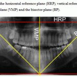
Horizontal reference plane [HRP]: a line drawn between the most external and superior points of the two condyles (figure 1).
Vertical reference plane [VRP]: the most external posterior point of the condyle was determined and a vertical line at 90 degree angle to the horizontal plane passing through this point was drawn (figure 1).
Bisector plane [BP]: a bisector line from the intersection point of both vertical and horizontal planes to median mandibular point (figure 1).
Median mandibular point: a point that obtained from the inferior central interincisive point (figure 1).
Vertical median plane [VMP]: a line drawn from median point parallel to the vertical plane (figure 1).
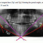
Tangents: Tg1 line drawn through the most dorsal points on the posterior surface of the condyle and the ramus. Tg2 line drawn through the borders of the most inferior outline of the body and the region of the mandibular angle (figure 3).
After drawing and tracing the previous lines and points the following relations were calculated:
Gonial angles formed by Tg1 and Tg2 lines.
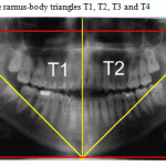
Ramus body triangles surface area (figures 2, 3):
Triangle 1 (impaction site): formed by HRP, right BP and VMP lines
Triangle 2 (non impaction site): formed by HRP, left BP and VMP lines
Triangle 3 (impaction site): formed by right BP, VRP and HRP lines
Triangle 4 (non impaction site): formed by left BP, VRP and HRP lines
Triangle 5 (impaction site): formed by right Tg1, right Tg2 and RBP lines
Triangle 6 (non impaction site): formed by left Tg1, left Tg2 and left BP lines 3-Mesiodistal crown width of mandibular third molar was measured as the greatest distance between the mesial and distal surfaces of the crown.
Data were collected and analyzed to find out whether there is a skeletal measurements difference between erupted and impacted third molar teeth areas.
Results
The computerized skeletal tracing measurements data were recorded and statistically analyzed using t- test for comparison between impaction and non impaction sites. Means and standard deviations for T1, T2, T3, T4, T5 and T6 triangles surfaces areas are shown in table 1. There is statistically significant decrease in the surface area of the impacted sites triangles T1, T3 and T5 compared to the non impaction site triangles T2, T4 and T6 as shown in table 2. There is no significant difference in mesiodistal width and gonial angles between impaction and non impaction sites as shown in table 3.
 |
Figure 1: Shows the horizontal reference plane (HRP), vertical reference plane (VRP), vertical median plane (VMP) and the bisector plane (BP).
|
 |
Figure 2: Shows the ramus-body triangles T1, T2, T3 and T4:
|
 |
Figure 3: Shows tangent lines (Tg1 and Tg2) forming the gonial angles, and the ramus-body triangles T5 and T6.
|
Table 1: Means and standard deviations of T1, T2, T3, T4, T5 and T6 triangles.
| Triangle | Mean surface area (cm2) | SD |
| T1 | 35 | 3.0 |
| T2 | 33.53 | 2.9 |
| T3 | 35 | 3.0 |
| T4 | 33.5 | 2.9 |
| T5 | 22.9 | 2.1 |
| T6 | 24.1 | 2.2 |
Table 2: t-test of T1-T2, T3-T4 and T5-T6 triangles.
| Triangles | t-test |
| T1-T2 | 0.025 |
| T3-T4 | 0.025 |
|
T5-T6 |
0.012 |
Table 3: Means and standard deviations of the mesiodistal widths of the third molars and the gonial angles of the impaction and non impaction sites.
| impaction site | non impaction site | ||||
| Mean | SD | Mean | SD | P- value | |
| Mesiodistal width | 12.7 mm | 2.2
|
12.6 mm | 2.3 | 0.96 |
| Gonial angle | 128.4º | 5.3 | 129.5º | 5.3 | 0.35 |
Discussion
The present study was performed to assess and compare the measurements of gonial angles, ramus body relation, and mesiodistal crown width between the area of impacted and erupted mandibular third molars determined from panoramic radiographs. Median mandibular line is directly related to the symmetry of the lower dental arch, which could indicate a better relation of the bone dental symmetry.
Habets was the first to propose an index for assessment of mandibular asymmetry [15]. A more recent method of symmetry estimation was proposed in 1994 by Kjelberg [16]. The system developed by Habets helps in the diagnosis of mandibular asymmetry, but does not determine which part of mandibular ramus is responsible for it, which limits its usefulness. Kjelberg index estimates the proportions between mandibular condyle and ramus. The method used in the present study used panorametry measurements described by Puricelli in 2009 [17].
The method presented in this study allows the analysis of the skeletal and dental median lines in the mandible independent of the rigid structures of the facial skeleton through horizontal and vertical reference planes. The results of this study showed that the mean values of gonial angle were 128.4o ± 5.3 and 129.5o ± 5.3 for impaction and non impaction sites respectively, with no significant difference between the two groups. The mean values of gonial angles in the present study are similar to that reported in many previous studies [14]. However, Shahabi et al., reported a gonial angle of 124.17o in the panoramic radiograph [12]. The disparity in this results compared to the present study results may be due to the conduction of the other study on class1 malocclusion subjects.
Determination of the median mandibular point allows the outline of what is called ramus body triangles. These triangles are contained within the limits of the mandibular area, and can associate the external and internal metrics of the mandibular body and ramus. Many studies have shown that in cases with impacted mandibular third molars, the alveolar arch space between the second molar and the ramus is considerably smaller than in areas where no impaction is present [18]. Two factors separately influence this: reduced growth in length of the mandible and vertical direction of condylar growth. The results of the present study showed a significant decrease in the mandibular length at the impaction sites compared to non impaction sites. These results are similar to that reported in some previous studies. However, Venta et al. concluded that no significant difference in mandibular length could be found between impaction and non impaction areas [19]. This may be due to the use of manual graphimetric method of cephalometric radiographs compared to the used method in this study which used more meticulous technique based on computer analysis of panoramic radiographs.
Conclusion
Sites with impacted mandibular third molars area exhibit shorter mandibular lengths than sites with erupted mandibular third molars. There is no statistically significant difference of gonial angles and mesiodistal widths between impacted and non impacted areas.
References
- Daley TD. Third molar prophylactic extraction: a review and analysis of the literature. Gen.Dent. 1996; 44: 310-20.
- Behbehani F, Artun J, Thalib L. Prediction of mandibular third-molar impaction in adolescent orthodontic patients. Am.J.Orthod.Dentofacial Orthop. 2006; 130: 47-55.
- Richardson ME. The etiology and prediction of mandibular third molar impaction. Angle Orthod. 1977; 47: 165-72.
- Castella P, Albright RH, Jr., Straja S, Tuncay OC. Prediction of mandibular third molar impaction in the orthodontic patient from a panoramic radiograph. Clin.Orthod.Res. 1998; 1: 37-43.
- Bjork A. Mandibular growth and third molar impaction. Acta Odontol.Scand. 1956; 14: 231-72.
- Akcam MO, Altiok T, Ozdiler E. Panoramic radiographs: a tool for investigating skeletal pattern. Am.J.Orthod.Dentofacial Orthop. 2003; 123: 175-81.
- Laster WS, Ludlow JB, Bailey LJ, Hershey HG. Accuracy of measurements of mandibular anatomy and prediction of asymmetry in panoramic radiographic images. Dentomaxillofac.Radiol. 2005; 34: 343-9.
- Mckee IW, Glover KE, Williamson PC, Lam EW, Heo G, Major PW. The effect of vertical and horizontal head positioning in panoramic radiography on mesiodistal tooth angulations. Angle Orthod. 2001; 71: 442-51.
- Niedzielska IA, Drugacz J, Kus N, Kreska J. Panoramic radiographic predictors of mandibular third molar eruption. Oral Surg.Oral Med.Oral Pathol.Oral Radiol.Endod. 2006; 102: 154-8.
- Legovic M. [The gonial angle and the growth of the craniofacial complex]. Acta Stomatol.Croat. 1983; 17: 205-11.
- Mattila K, Altonen M, Haavikko K. Determination of the gonial angle from the orthopantomogram. Angle Orthod. 1977; 47: 107-10.
- Shahabi M, Ramazanzadeh BA, Mokhber N. Comparison between the external gonial angle in panoramic radiographs and lateral cephalograms of adult patients with Class I malocclusion. J.Oral Sci. 2009; 51: 425-9.
- Thompson GW, Popovich F. Static and dynamic analyses of gonial angle size. Angle Orthod. 1974; 44: 227-34.
- Xie QF, Ainamo A. Correlation of gonial angle size with cortical thickness, height of the mandibular residual body, and duration of edentulism. J.Prosthet.Dent. 2004; 91: 477-82.
- Habets LL, Bezuur JN, van Ooij CP, Hansson TL. The orthopantomogram, an aid in diagnosis of temporomandibular joint problems. I. The factor of vertical magnification. J.Oral Rehabil. 1987; 14: 475-80.
- Kjellberg H, Ekestubbe A, Kiliaridis S, Thilander B. Condylar height on panoramic radiographs. A methodologic study with a clinical application. Acta Odontol.Scand. 1994; 52: 43-50.
- Puricelli E. Panorametry: suggestion of a method for mandibular measurements on panoramic radiographs. Head Face.Med. 2009; 5: 19.
- Hattab FN, Alhaija ES. Radiographic evaluation of mandibular third molar eruption space. Oral Surg.Oral Med.Oral Pathol.Oral Radiol.Endod. 1999; 88: 285-91.
- Venta I, Turtola L, Ylipaavalniemi P. Radiographic follow-up of impacted third molars from age 20 to 32 years. Int.J.Oral Maxillofac.Surg. 2001; 30: 54-7.

This work is licensed under a Creative Commons Attribution 4.0 International License.


