How to Cite | Publication History | PlumX Article Matrix
Soil Body Formation in Front of the Rotary Tillage Tools
Maxat Amantaiuly Amantayev1 , Gayaz Zakirovich Gaifullin2, Valentina Gennadevna Kushnir2, Serik Zakirovich Nurushev2 and Ruslan Ivanovich Kravchenko2
1S.Seifullin Kazakh Agro Technical University, Kazakhstan, 010000, Astana, Prospect Pobedy, 62.
2Kostanay State University A.Baitursynov, Kazakhstan, 110000, Kostanay, Abay avenue, 28.
DOI : http://dx.doi.org/10.13005/bbra/2353
ABSTRACT: In this paper are presented the results of the experimental researches being carried out under controlled soil bin conditions to study the soil-free rolling rotary tillage tools interaction. There were investigated six different types of the rotary tillage tools. Observations showed that during the operation in front of the working surface of all rotary tillage tools the compacted soil bodies are built up. Cross section of the fixed soil bodies has the configuration of wedge of two types. The first type of the soil wedge is characterized by the apical angle equaled 90º–φ1 where φ1 is the soil internal friction angle. This type of soil bodies is built up on the working surface which is limited in height. Cross section of the soil bodies fixed in front of the interface of the solid tillage tools has the configuration of wedge of the second type; its parameters are widely varied depending on the sweep and tilt angles. The quality of the work and dynamics of the tillage implements depend on the generated soil body parameters rather than the design parameters of the tillage tools.
KEYWORDS: rotary tillage tool; disc tillage tool; soil body formation; fixed soil body; soil wedge; soil wedge parameters
Download this article as:| Copy the following to cite this article: Amantayev M. A, Gaifullin G. Z, Kushnir V. G, Nurushev S. Z, Kravchenko R. I. Soil Body Formation in Front of the Rotary Tillage Tools. Biosci Biotech Res Asia 2016;13(4). |
| Copy the following to cite this URL: Amantayev M. A, Gaifullin G. Z, Kushnir V. G, Nurushev S. Z, Kravchenko R. I. Soil Body Formation in Front of the Rotary Tillage Tools. Biosci Biotech Res Asia 2016;13(4). Available from: https://www.biotech-asia.org/?p=17309 |
Introduction
Soil tillage implements are most widely used and play an important role in agriculture. They perform different operations from soil manipulation to weeds control through cutting. As a working part the passive and rotary tillage tools are used. Passive tools execute only forward motion whereas the rotary ones also rotate on its axis. Under certain circumstances and conditions in front of the working surface of the tillage tools the fixed soil bodies are built up. There are the following three cases:
Soil adhesion on the surface of the cultivating tool in the case of the tillage of the soil in adhesive plastic consistency [1, 2, 3];
The compacted soil body formation during the cutting of the cohesive soil medium [1, 4, 5, 6, 7, 8];
The fixed soil wedge formation on the shear surface during the soil failure pattern in non-sliding soil conditions [1, 9];
The first case takes place during the wet soil tillage, the second case – during the pure cutting of the cohesive soil medium. The most common is the third case. There have been studied the soil body formation in front of the vertical wide and narrow tines with different rake angles [1, 9, 10, 11].
Rotary tillage tools, passively driven by the forces of the soil reaction, can ride over stumps and obstacles on the soil surface. Moreover, rotary tillage tools can be operated over wide range of soil depth and offer notable advantages in reduced tillage operations within the conservation tillage systems.
Rotary tillage disc tools have been studied by many researchers, in particular, Nartov, P.S., 1972 [12], Kanarev, F.M., 1983 [13], Abo El Ees, N.A.E.H. and etc., 1986 [14], Godwin and etc., 1987 [15], O’Dogherty, M.J. and etc., 1996 [16], Hettiaratchi, D.R.P., 1997 [17, 18, 19, 20], Nalavade P.P. and etc., 2010 [21] etc. Many of them studied the geometrical and kinematic parameters of the disc, evaluated the field performances of the disc and measured the soil resistance forces acting on the tillage tool. However, variety of studies was not focused on the soil body formation phenomenon in front of the rotary tillage tools interface. There were only indirect verifications of the existence of such process [19, 21, 22].
Hence, this research is aimed to study the soil body formation on the working surface of the rotary tillage tools rotating under the active forces of the soil.
Material and methods
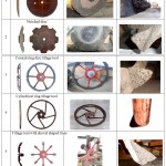
The experimental research studies of the soil-rotary tillage tools interaction were carried out under controlled soil bin conditions. There were investigated six different types of the free rolling rotary tillage tools, in particular, standard spherical and notched discs of harrow, conical ring disc tillage tool, cylindrical ring tillage tool, rotary tillage tool with shovel shaped tines for incorporating the weed seeds and blade tillage tool of the rotary harrow (Table 1).
The soil moisture content was 26%, the cone index 1,1 MPa. Soil internal friction angle varied between 29-37º. Soil bin was filled with the soil in length to 85%. Unfilled part of the soil bin is used for measuring the fixed soil body parameters.
Each test run was replicated four times. Rotary tillage tool, set at an angle to the direction of the travel, was moved at 1 m/s forward speed and 8-10 cm working depth and rotated under the active forces of the soil. All tillage tools operated in non-scouring soil without using scrappers.
The results of observations showed that in front of the working surface of all investigated rotary tillage tools the fixed soil bodies are built up (Table 1). After each test run they were photographed. For doing so, the cross section of the fixed soil body was cut perpendicular to the working surface of the tillage tool. These cross sections are illustrated in Table 1. Then the photographs were transferred to the computer for measuring the cross section parameters of the soil body on an appropriate scale.
 |
Table 1: Types of the investigated rotary tillage tools with the fixed soil bodies in front of their working surfaces |
The results and discussion
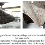
Cross sections of the compacted soil bodies in front of the rotary tillage tool have the configuration of wedge of two types (Table 1). The first type is built up on the working surface which is limited in height. They are conical ring disc tillage tool (#3), cylindrical ring tillage tool (#4) and rotary tillage tool with shovel shaped tines (#5). This type of the soil wedge is characterized by the following (Figure 1,а). As shown in figure ABC represents the soil wedge built up on the working surface of the tillage tool #5. The apical angle of the wedge B equals 90º–φ1, where φ1 is the soil internal friction angle. This type of soil wedge formation takes place in soil deformation during the inclined penetration of the shear element.
 |
Figure 1: Cross sections of the soil bodies in front of the rotary tillage tools |
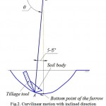
Radius-vector ОА1 of the considered point A of the tillage tool interface is penetrated into the soil when θ=40…130º (Figure 2). At θ=90º it reaches the bottom point of the furrow. From the graph of effect of the angle of turning [theta] on the total resistance P to the soil deformations is seen that it reaches the maximum value when θ=80º, i.e. 10º before the bottom point of the furrow (Figure 3) [23].
Soil body formation occurs in the zone of the greatest soil strength on the surface of the rotary tillage tool, or in the zone of maximum resistance to the soil deformations. This zone is in the range of the turning angle of radius-vector OA 5-15º before the bottom point of the furrow (Figure 2). In this period tillage tool continues the motion with inclined direction, i.e. it operates in the mode of inclined penetration of the shear element.
 |
Figure 2: Curvilinear motion with inclined direction of the tillage tool in the period of the soil wedge formation |
![Figure 3: Effect of the angle of turning [theta] of the radius-vector ОА on the total resistance P to the soil deformations (in %)](https://www.biotech-asia.org/wp-content/uploads/2016/12/Vol_13_no4_Soil_Seif_fig3-150x150.jpg) |
Figure 3: Effect of the angle of turning [theta] of the radius-vector ОА on the total resistance P to the soil deformations (in %) |
During the experiments the apical angle В of the soil wedge varied between 54-60º. In the field conditions the soil wedge density reaches 2,2-2,4 g/cm3 which is 1,8-2,1 times greater than the undisturbed soil density.
The second type of the soil wedge (Figure 1,b) is built up in front of the interface of the solid tillage tools. They are the standard spherical and notched discs of harrow (#1 and #2) and blade tillage tool of the rotary harrow (#6). In figure 1,b the ABC represents this type of the soil wedge. The apical angle В is varied in wide range depending on the sweep and tilt angles. In experiments it varied between 48-91º. Such wide range is explained as follows. All the elements of the disc surface consequently pass through the period of 10-15º before the bottom point (Figure 2). During the passage of this period the soil body which has the configuration of wedge in cross section is built up on each element. The sum of all these wedges gives one generalized wedge ABC. The wedge parameters depend on many factors and revealing these dependences at present is complicated.
The sizes of the soil wedge of the second type are several times greater than the corresponding parameters of the first type wedge. For instance, its average cross section area equals 23,8 cm2, which is more than 5 times greater than the area of the first type wedge (Table 2).
Table 2: Cross section area of the soil body on the surface of the tillage tools
| Indexes | Cross section area of the soil wedges S, cm2 | |
| Type 1 | Type 2 | |
| Arithmetical mean value ẋ | 4,5 | 23,8 |
| Dispersion D | 1,3 | 6,3 |
| Standard deviation σ | 1,1 | 2,5 |
| Coefficient of variation V | 25,2 | 10,5 |
During the soil-rotary tillage tools interaction the fixed soil bodies are always, in all types of soils, built up on their working surface. They are beneath the soil surface and invisible to observers. They can be detected only by specially conducted experiments. The undisturbed soil is deformed by the fixed soil body surface instead of the rotary tillage tools interface. The quality of the work and dynamics of the tillage implements depend on the generated soil body parameters rather than the design parameters of the tillage tools.
The temporary soil bodies are accumulated during the tillage of the dry and sandy soils. They exist only in the period of penetration of the tillage tools into the soil. During the lifting the soil bodies are fallen to pieces. The fixed soil bodies are formed in front of the rotary tillage tools surface when wet and clay soils are tilled. After lifting the tillage tool these soil bodies are not broken up.
Conclusion
The results of the research study revealed that during the operation the fixed soil bodies are always, in all types of soils, built up in front of the working surface of all free rolling rotary tillage tools. There can be accumulated temporary and fixed soil bodies depending on the soil type and its moisture content. Cross section of the soil bodies has the configuration of wedge of two types. The first type of the soil wedge is characterized by the apical angle equaled 90º–φ1. This type of soil bodies is built up in front of the working surface which is limited in height. In other cases the cross section has the configuration of wedge of the second type, which parameters are widely varied. The soil bodies of the second type are the more than 5 times larger than those of the first type.
References
- Koolen, A.J. and H. Kuipers, 1983. Agricultural soil mechanics. Springer. Verlag, New York, pp: 241.
- Bahtin, P.U., 1969. The research of the physical and mechanical and technological properties of the main types of the soil of USSR. Моscow: Kolos, pp: 271.
CrossRef - Putrin, A.C., 2003. Basics of development of tillage tools for soils that is beyond the physically tilth condition, PhD thesis, OSAU, Orenburg.
- Vetrov, Y.L., 1971. Soil cutting with earth moving machines. Moscow: Mashinostroenie, pp: 357.
- Zelenin, A.N., 1959. Soil cutting. Moscow: Izdanie Academii Naul USSR, pp: 360.
- Trufanov, V.V., 1989. Deep chiseling the soil. Moscow: Agropromizdat, pp: 140.
- Kostritsyn, A.K., 1956. Cutting of a cohesive medium with knives and cones. Proceedings on soil mechanics, Mashinostroenie (No. 3), pp: 5-18.
- Panov, I.M. and V.I. Vetohin, 2008. Physical basics of the soil mechanics. Kiev: Fenix, pp: 265.
- Gaifullin, G.Z. and A.A. Kurach, 2003. Soil wedge formation on the shear surface of the tine. Techniques in Agriculture, 4: 7.
- Godwin, R.J. and G. Spoor, 1977. Soil failure with narrow tines. J. Agric. Engng. Res., 22: 213-228.
CrossRef - Aluko, O.B. and D.A. Seig, 2000. An experimental investigation of the characteristics of and conditions for brittle fracture in two-dimensional soil cutting. Soil and Tillage Research, 57: 143-157.
CrossRef - Nartov, P.S., 1972. Disc tillage implements. Voronezh: Izdatel’stvo Voronezhskogo universiteta, pp: 181.
- Kanarev, F.M., 1983. Rotary tillage machines and implements. Moscow: Mashinostroenie, pp: 144.
- Abo El Ees, N.A.E.H. and B.M.D. Wills, 1986. An analysis of the geometric parameters of a curved vertical disc. J. Agric. Engng. Res., 35: 277-286.
CrossRef - Godwin, R.J., D.A. Seig and M. Allott, 1987. Soil failure and force prediction for soil engaging discs. Soil Use and Management, 3(Vol.3): 106-114.
- O’Dogherty, M.J., R.J. Godwin, M.J. Hann and A.A. Al-Ghazal, 1996. A geometrical analysis of inclined and tilted spherical plough discs. J. Agric. Engng. Res., 63: 205-218.
CrossRef - Hettiratchi, D.R.P., 1997. Predicting the draught requirements of concave agricultural discs. Journal of Terramechanics, 3(Vol.34): 209-224.
- Hettiaratchi, D.R.P., 1997. The soil contact zones of concave agricultural discs: Part 1, Theoretical analysis. J. Agric. Engng. Res., 67: 113-125.
CrossRef - Hettiaratchi, D.R.P., 1997. Prediction of soil forces acting on concave agricultural discs. J. Agric. Engng. Res., 68: 51-62.
CrossRef - Hettiaratchi, D.R.P. and M.M. Alam, 1997. Calculation, validation and simulation of soil reactions on concave agricultural discs. J. Agric. Engng. Res., 68: 63-75.
CrossRef - Nalavade, P.P., V.M. Salokhe, T. Niyamapa and P. Soni, 2010. Performance of free rolling and powered tillage discs. Soil and tillage research, 109: 87-93.
CrossRef - Alam, M.M., 1989. Soil reaction forces on agricultural disc implements, PhD thesis, University of Newcastle upon Tyne, Newcastle.
- Gaifullin, G.Z., 2003. Mechanical and technological basics for the development and improvement of the tillage tools of machines for conservation farming, PhD thesis, CSAA, Chelyabinsk.

This work is licensed under a Creative Commons Attribution 4.0 International License.


